Home Support Selection Guide
TECHNICAL SUPPORT

Product Support

Catalogue

Resources for Engineers
Servo
What’s a Servo Motor, Anyway? Servo motors are the unsung heroes of precise motion. Unlike regular motors that spin freely, servos rotate to specific angles (typically 0–180 degrees) based on electrical signals. The MG995 stands out for its torque (10 kg/cm!) and metal gears, making it ideal for heavy-duty tasks like robotic arms or steering mechanisms. But none of that matters if you can’t wire it correctly. The Three Wires That Rule the World Pop open the MG995’s connector, and you’ll find three wires: Brown (Ground): The foundation. Connect this to your circuit’s ground. Red (Power): The lifeblood. Requires 4.8–7.2V—usually a 5V supply. Orange/Yellow (Signal): The conductor’s baton. This wire listens for PWM (Pulse Width Modulation) signals to determine position. But here’s where beginners stumble: voltage isn’t negotiable. Use a weak power supply, and the servo jitters. Overpower it, and you’ll smell regret. A 5V/2A adapter or a dedicated battery pack (like a 6V NiMH) is your safest bet. The PWM Secret Sauce The MG995’s brain responds to PWM pulses sent to the signal wire. Here’s the cheat code: 1 ms pulse: 0 degrees (full left) 1.5 ms pulse: 90 degrees (neutral) 2 ms pulse: 180 degrees (full right) These pulses repeat every 20 ms (50 Hz frequency). Think of it like a metronome for motion—each beat tells the servo where to snap. Wiring to Microcontrollers: Arduino Example Let’s get hands-on. Wiring the MG995 to an Arduino Uno? Easy: Brown wire → GND pin Red wire → 5V pin (or external power) Orange wire → Digital PWM pin (e.g., D9) But here’s a pro tip: Don’t power the servo through the Arduino’s 5V pin. The MG995 can draw up to 1.2A under load, which fries most boards. Use an external supply and share the ground. ```cpp include Servo myServo; void setup() { myServo.attach(9); // Signal pin on D9 } void loop() { myServo.write(90); // Neutral position delay(1000); myServo.write(180); // Full right delay(1000); } ### Why Bother With the Pinout? Glad you asked. Miswiring leads to: - Jittery movement: Weak power or noisy signals. - Overheating: Incorrect voltage or blocked movement. - Silent death: Reversed polarity (brown/red swapped). Master the pinout, and you’ll dodge these pitfalls like Neo in *The Matrix*. From Theory to Triumph—Real-World Applications Now that you’ve nailed the MG995’s pinout, let’s turn knowledge into action. This servo isn’t just for hobbyists; it’s a workhorse in industrial prototypes, animatronics, and even camera gimbals. ### Case Study: Robotic Arm for Pick-and-Place Imagine building a robotic arm to sort objects. You’d need: - 2–4 MG995 servos (for joints/gripper) - Arduino/Raspberry Pi - External 6V battery pack Wiring Strategy: - Daisy-chain ground/power wires to a common supply. - Dedicate separate PWM pins for each servo. But here’s the catch: *Multiple servos = power-hungry beasts*. A 6V/3A supply ensures smooth operation. ### Raspberry Pi Integration The Pi’s GPIO pins can’t natively output PWM signals. Solution: Use Python’s `RPi.GPIO` library for software PWM or a hardware PCA9685 module for precision. python import RPi.GPIO as GPIO import time GPIO.setmode(GPIO.BCM) SIGNAL_PIN = 18 GPIO.setup(SIGNALPIN, GPIO.OUT) pwm = GPIO.PWM(SIGNALPIN, 50) # 50 Hz def set_angle(angle): duty = (angle / 18) + 2 pwm.ChangeDutyCycle(duty) pwm.start(0) set_angle(90) # Neutral time.sleep(2) pwm.stop() GPIO.cleanup() ``` Troubleshooting 101 Problem: Servo doesn’t move. Fix: Check connections with a multimeter. Is the signal wire sending pulses? Use an oscilloscope or LED test circuit. Problem: Servo buzzes at rest. Fix: Add a 100µF capacitor across power/ground to smooth voltage spikes. Problem: Limited range of motion. Fix: Calibrate PWM pulse widths in code. Some servos respond to 0.5–2.5 ms pulses for extended range. Pushing Boundaries: Modding the MG995 Daredevils often hack servos for continuous rotation: Remove the physical stop block inside. Disconnect the potentiometer feedback. Rewire for 360-degree spinning (now it’s a gearmotor!). But be warned: This voids warranties and requires soldering finesse. Final Thoughts The MG995’s pinout is your gateway to mechanical wizardry. Whether you’re building a solar tracker or a Halloween animatronic, understanding those three wires transforms you from a button-pusher to a creator. Now go forth and make something that moves—literally.
Technical Insights
Micro Servo

Selection Guide

Published 2025-07-22

How many parts of Servo Motors?


外壳(Case)

 
1.  舵机的外壳有上壳、中壳、底壳三个部分。舵机的外壳一般是塑料的,特殊的舵机可能会有金属铝合金外壳。
2. 金属外壳能够提供更好的散热,可以让舵机内的电机运行在更高功率下,以提供更高的扭矩输出。金属外壳也可以提供更牢固的固定位置。
常用的塑胶外壳的材料是POM或尼龙加纤。也有一些例外,比如9克舵机蓝色外壳是PC,黑色外壳是ABS+PC。常用的金属外壳材料是铝。
 
产品参数 定义
测试1 222 222
扭矩 11 22


  1. 不同壳体的优缺点

塑料外壳有质量轻、成本低的优点,因此大部分舵机使用的都是塑料的外壳。但是塑料外壳也有散热差、强度低、保护效果不好的缺点。
和塑料外壳相比,金属外壳有更好的散热效果和强度。但是金属壳体由于材料成本高、加工工艺复杂(大多是CNC),只能使用在高端舵机上。后来为了平衡舵机的性能和价格,出现了只有中壳采用金属壳的半铝舵机。

减速齿轮组(Gearbox / Reducer)

说明不同的齿轮分类,不同种类的寿命和价格对比。
输出轴(Output shaft)
 
  1. 常见的齿轮种类

 
  1. 金属齿(Metal gear)

金属齿常用的材料有:铜、铝、钢、钛合金。最常用的材料是铜。
 
  1. 塑胶齿(Plastic gear)

塑胶齿常用的材料有:POM、PE、TPEE;

电位器(Position sensor / Potentiometer)

 
  1. 常见的电位器种类

圆形电位器、方形电位器、磁编码位置传感器。
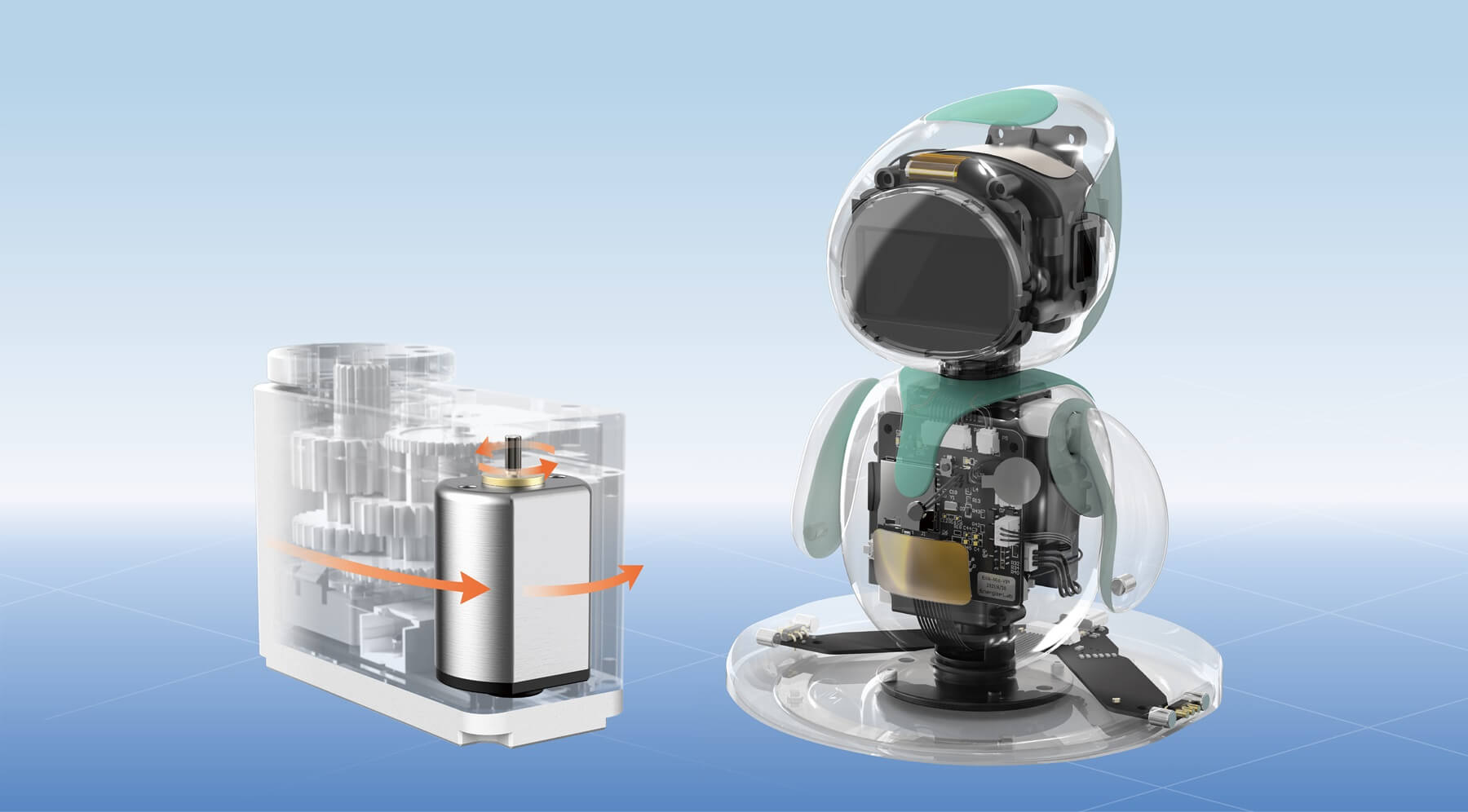
 

电机/马达(Motor)

电机在舵机中作用是给舵机提供转动的力,当电机转动时,通过马达齿带动一级齿转动,逐级传递,最终带动输出齿转动。
舵机内部使用的电机有:直流有刷铁芯电机、直流有刷空心杯电机、直流无刷电机。三种电机的对比如下:
  1. 直流有刷铁芯电机:

    • 优点:成本低。大部分舵机使用的都是有刷铁芯电机。
    • 缺点:寿命短、响应速度慢、效率低等;
  1. 直流有刷空心杯电机

      空心杯电机也称无铁芯电机。相同尺寸下,它能够实现比有刷电机更大的扭矩,寿命也更长,但是伴随着发热的问题,因此空心杯电机大多配合铝壳使用。
    • 优点:效率高、响应快、寿命长、能量密度大等;
    • 缺点:发热严重;
  1. 直流无刷电机

      使用有刷电机的舵机寿命主要受到电机的限制,转动过程中电刷一直在和换向器摩擦,由于电刷的损耗,电机的寿命会急剧减少。无刷电机没有了电刷结构,寿命往往是有刷电机的好几倍。
    • 优点:效率高、寿命长、噪音低;
    • 缺点:价格贵。因此大扭力小体积的高端舵机才会使用无刷电机。
 

控制电路(Motor control board)

 
  1. 硬件(PCB)


  1. 固件(Firmware)

Update Time:2025-07-22

Powering The Future

Contact Kpower's product specialist to recommend suitable motor or gearbox for your product.

Mail to Kpower
Submit Inquiry
WhatsApp Message
+86 180 0277 7165
 
kpowerMap