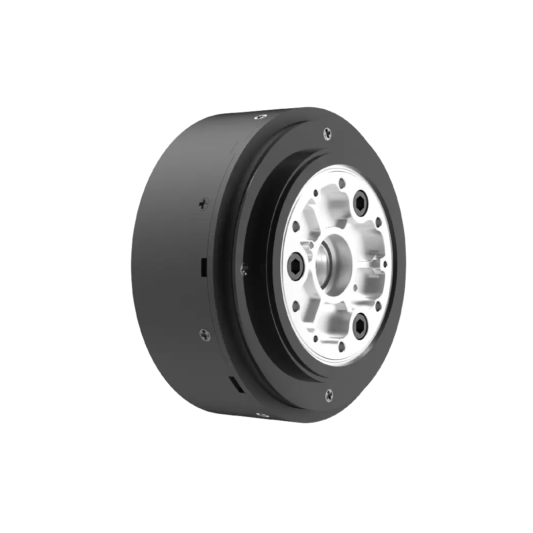
The Silent Power of Sensorless BLDC Motors
Imagine a world where machines move with the quiet precision of a whisper, yet pack the raw power of a storm. This is the realm of brushless DC (BLDC) motors—devices that have transformed industries from drones to electric vehicles. But what happens when you strip away the sensors, those tiny components that traditionally tell the motor where its rotor is? You get a sleeker, cheaper, and more resilient beast: the sensorless BLDC motor. And when paired with an Arduino, this duo becomes a playground for innovators.

Why Go Sensorless? BLDC motors are prized for their efficiency and longevity, but their reliance on Hall-effect sensors has drawbacks. Sensors add cost, complexity, and points of failure. Enter sensorless control, a method that reads the motor’s back-electromotive force (back-EMF) to infer rotor position. It’s like teaching the motor to “feel” its way through motion, much like a bat navigates using echolocation. The result? A lighter, cheaper motor that thrives in harsh environments (think dust, moisture, or vibrations) where sensors might falter.
Arduino: The Brain Behind the Brawn Arduino’s open-source ecosystem democratizes technology. With libraries like SimpleFOC and VESC_ESC, even hobbyists can program sensorless BLDC motors without wrestling with complex math. The Arduino Uno or Nano’s PWM pins send signals to an electronic speed controller (ESC), which handles the heavy lifting of switching motor phases. The real magic lies in the code—algorithms that measure back-EMF zero-crossing points to keep the motor in sync.
A Starter Project: Spin It Up Let’s build a basic sensorless BLDC setup. You’ll need:
Arduino Uno Sensorless BLDC motor (e.g., Turnigy Aerodrive SK3) BLDC ESC (e.g., Hobbywing XRotor) Potentiometer (for speed control)
Wire the ESC to the Arduino’s PWM pin, connect the potentiometer to an analog input, and upload a sketch that maps potentiometer values to motor speed. The ESC uses back-EMF data to adjust phase currents, ensuring smooth rotation. Within minutes, you’ve created a responsive, sensorless system—no PhD required.
The Challenges: Why It’s Not All Smooth Sailing Sensorless control isn’t perfect. At low speeds, back-EMF is weak, making rotor detection tricky. Some workarounds include “kick-starting” the motor with a predefined sequence or using advanced algorithms like field-oriented control (FOC). But here’s where Arduino shines: its community-driven libraries abstract these complexities, letting you focus on creativity rather than calculus.
Real-World Impact: From Hobbyists to Heroes Consider solar trackers that adjust panels without costly sensors, or underwater drones that eliminate leak-prone wiring. One maker even built a sensorless ebike motor using Arduino, slashing costs by 40%. The implications are vast—cheaper automation, sustainable energy systems, and robotics that push boundaries.
By marrying Arduino’s accessibility with sensorless BLDC efficiency, we’re not just tinkering—we’re redefining what’s possible.
Pushing Boundaries with Code and Creativity
In Part 1, we explored the basics of sensorless BLDC control. Now, let’s dive deeper into the code, hacks, and futuristic applications that make this combo a game-changer.
Advanced Control: Field-Oriented Control (FOC) For smoother operation, FOC algorithms treat the motor’s magnetic fields like vectors, optimizing torque and efficiency. Libraries like SimpleFOC bring FOC to Arduino, enabling sensorless precision once reserved for industrial machinery. Imagine a 3D printer with near-silent motion or a robotic arm that moves with balletic grace—all achievable with an Arduino and some ingenuity.
Beating the Low-Speed Problem Stalling at startup? Try “six-step commutation”: pulse the motor phases in a set sequence until it spins fast enough to generate detectable back-EMF. Alternatively, integrate an inertial measurement unit (IMU) to estimate position during startup. One engineer combined Arduino with a TinyML model to predict rotor alignment, proving that machine learning can breathe new life into old techniques.
Case Study: The Self-Tuning Motor A Berlin-based startup created an open-source ventilator during the COVID pandemic using sensorless BLDC motors and Arduino. The motors adjusted airflow based on patient needs, with self-tuning code that compensated for load changes. This project highlighted how sensorless systems could adapt dynamically—no manual calibration needed.
DIY Electric Vehicle: A Step-by-Step Guide Ready to scale up? Let’s build a sensorless BLDC-driven go-kart:
Motor: 48V 1000W sensorless BLDC (e.g., QS Motor). Controller: Arduino Mega + VESC-based ESC. Throttle: Hall-effect pedal connected to an analog input. Battery: Lithium-ion pack with a BMS for safety.
The Arduino reads throttle input, sends speed commands to the ESC, and monitors battery voltage. Add a dashboard using an OLED display, and you’ve got a vehicle that’s both powerful and intelligent.
The Future: Where Do We Go From Here? As Arduino boards gain processing power (look at the GIGA R1 WiFi), sensorless systems will tackle even bigger challenges. Think swarm robotics with motors that “talk” to each other or smart factories where machines self-diagnose faults via back-EMF patterns. Researchers are also exploring sensorless motors for prosthetics, using subtle current changes to predict user movement—a fusion of biology and engineering.
Conclusion: Your Turn to Innovate Sensorless BLDC motors and Arduino are more than tools—they’re invitations to rethink the ordinary. Whether you’re crafting a quiet desk fan or a solar-powered rover, the only limit is your curiosity. So grab a motor, fire up the IDE, and join the revolution where code meets motion. The future isn’t just automated; it’s alive with possibility.


